

Wondering if you are using enough voltage, wire feed speed, or how to set up pulsed MIG? This guide covers every critical MIG welding setting you need for consistent, full-penetration welds that look as good as they perform.
Most welding defects come down to machine settings, not necessarily skill. For beginners, we also designed MIG welding settings charts for each critical setting selection.
MIG Welding Essentials: Wire Feed Speed And Voltage
Wire feed speed (WFS) and voltage are the two most important MIG welding settings. Amperage, heat input, bead profile, spatter levels, and most other variables are a downstream consequence of how these two interact.
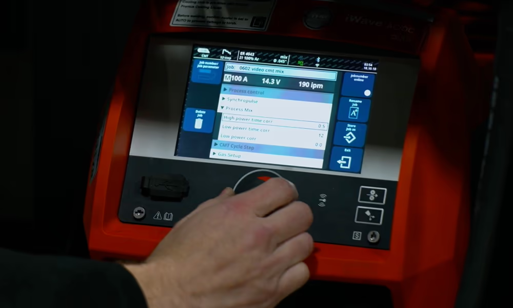
High-quality, industrial-grade MIG welders like those from Fronius automatically set the correct welding parameters. However, it’s still important to understand the core concepts of welding parameters.
Voltage
- Voltage controls the arc length and arc stability.
- Higher volts produce a wider, flatter bead with a longer arc.
- Too much voltage and you get excessive spatter, porosity, and an erratic arc.
- Too little and the wire stubs into the puddle, causing a harsh, popping arc and poor fusion.
Wire feed speed
- Wire feed speed determines how fast the consumable electrode is fed into the arc.
- Because the welding machine self-regulates to burn off wire at the rate it’s fed, WFS directly controls amperage — faster feed, more amps, more heat input.
- Too high and you burn through or get a convex, ropey bead.
- Too low and you get poor fusion and an unstable arc.
Voltage and WFS must remain in proportion. If you increase one without adjusting the other, weld quality degrades quickly. Think of it as a ratio you’re constantly fine-tuning, not two independent dials.
MIG Welding Settings for Mild Steel Chart
The chart below assumes short circuit transfer except spray transfer for the 1/2″ inch thick steel. Every power source will be different, but these ranges are a good starting point.
Wire Diameter | Material Thickness | WFS (IPM) | Voltage (V) | Gas |
0.023″ | 22–18 ga | 145-175 | 16-16.5 | 75/25 Ar/CO2 |
0.030″ | 18–12 ga | 150-360 | 17-18 | 75/25 Ar/CO2 |
0.035″ | 12 ga–3/16″ | 250-340 | 17-19 | 75/25 Ar/CO2 |
0.035″ | 3/16″–1/4″ | 320-380 | 18-22 | 75/25 Ar/CO2 |
0.035″ | 1/4″–5/16” | 360-420 | 21-22 | 75/25 Ar/CO2 |
0.045″ | 5/16”–3/8″ | 210-270 | 21-24 | 75/25 Ar/CO2 |
0.045″ | 3/8″–1/2″ | 220-390 | 23-30 | 98/2 Ar/O2 |
MIG Welding Settings for Stainless Steel
Shielding gas: Tri-mix (Short-circuit) | Shielding gas: 98% Ar + 2% O2 (Spray Arc) | ||||
Wire Diameter | Material Thickness | WFS (IPM) | Voltage (V) | WFS (IPM) | Voltage (V) |
0.035″ | 18 ga-14 ga | 120-270 | 19-21 | – | |
0.035″ | 14–12 ga | 230-325 | 20-21 | – | |
0.035″ | 12 ga–3/16″ | 300-375 | 20-21 | 400-420 | 23-24 |
0.035″ | 3/16″–1/4″ | 350-425 | 20-21 | 400-475 | 23-25 |
0.045″ | 1/4″–5/16” | 220-250 | 21-23 | 230-300 | 23-25 |
1/16″ | 3/8″–1/2″ | – | 140-230 | 25-32 | |
MIG Welding Settings for Aluminum
Wire Diameter | Material Thickness | WFS (IPM) | Voltage (V) | Gas |
0.030″ | 5/64”-1/8″ | 460-580 | 18-22 | 100% Argon |
0.035″ | 1/8″-3/16” | 350-450 | 21-24 | |
3/64″ | 1/4″–5/16” | 350-425 | 24-27 | |
3/64″ | 5/16”–3/8″ | 400-480 | 26-28 | |
1/16″ | 1/2″+ | 290-310 | 29-30 |
MIG Transfer Modes: Short Circuit, Globular, And Spray Arc
The ratio of WFS to voltage determines which transfer mode the arc operates in. Each mode has distinct characteristics and is suited to different applications.
Short circuit transfer occurs at lower WFS and voltage settings. The welding wire physically contacts the workpiece, short circuits, and melts in rapid succession. It’s well-suited to thin materials and out-of-position welding, but penetration is limited.
Globular transfer occurs in the transition zone between short circuit and spray. Metal transfers in large, irregular droplets that are difficult to control with significant spatter. It is generally a mode to pass through rather than weld in intentionally.Spray transfer requires higher voltage, higher WFS, and a shielding gas with at least 80% argon. Metal transfers as a fine, directed stream of small droplets with no short circuiting. It produces excellent penetration, clean weld beads, and less spatter. It’s limited to flat and horizontal positions on thicker material.
Transfer Mode | Voltage Range (V) | WFS Range (IPM) | Shielding Gas | Typical Material Use | Material Thickness |
Short-Circuit | 16-24 | 100-250 | 75/25 Ar/CO2, 100% CO2, and Tri-Mix for stainless | Mild steel and stainless steel. | Thin to medium |
Globular | 20-28 | 150-300 | 100% CO2 | Mild steel only | Medium to thick |
Spray | 18-33 | 200-500+ | 80+ Argon for mild steel, 98/2 Ar/O2 for stainless, and pure argon for aluminum | All metals. Especially important for aluminum. | Medium and thick |
The table above shows general values for using different transfer modes. The actual parameters can vary due to power source differences and wire diameter.
MIG Shielding Gas Selection And Flow Chart
Shielding gas protects the weld from atmospheric contamination and affects arc stability, spatter, bead profile, penetration, and arc transfer. Choosing the wrong welding gas or applying incorrect flow will affect the welding outcome, negating the proper parameters and technique you apply.
Material | Transfer Mode | Recommended Gas | Flow Rate (CFH)* | Critical Notes |
Mild steel | Short circuit | 75/25 Ar/CO2 | 20-35 | Most versatile mix for steel |
100% CO2 | 20-35 | More spatter, deeper penetration, lower cost | ||
Spray | 90%+ Ar/CO2 | 35-50 | Minimum 80% Ar to achieve spray | |
Stainless steel | Short circuit | Tri Mix: 90% He/8% Ar/2% CO2 | 40-50 | Tri-mix can require high CFH to compensate for helium low density. |
Spray | 98% Ar/2% O2 | 35-50 | O2 stabilizes arc, maintains corrosion resistance | |
Aluminum | Spray | 100% Ar | 35-55 | Pure argon only, higher flow for larger nozzles |
* CFH (Cubic feet per hour).
The table above shows a range. The actual values will depend on the welded environment (wind drafts), the nozzle size, position, and the welding speed. Make sure to observe for signs of insufficient or excessive flow rate:
Insufficient gas flow:
- Porosity. Visible or subsurface gas pockets in the finished weld
- Surface oxidation and discoloration, particularly on stainless and aluminum
- Rough, contaminated bead appearance
- Embrittlement in the heat affected zone on sensitive materials
Signs of excessive gas flow:
- Porosity despite adequate gas supply — often misdiagnosed as insufficient flow
- Erratic arc behavior caused by turbulence at the nozzle
- Excessive spatter without a clear settings-related cause
- Visible weld contamination that doesn’t improve when flow is increased further
Pulsed MIG Welding Settings
Pulsed MIG is a modified spray transfer process where the power source rapidly alternates between a high peak current and a low background current. This delivers the penetration and deposition benefits of spray transfer while keeping average heat input low enough to weld thinner materials and out-of-position joints that standard spray cannot handle.Pulsed MIG is highly beneficial for heat sensitive materials like stainless. See the animation below to understand how Pulsed MIG reduces heat input. To understand why this is critical for stainless, read our full guide on MIG welding stainless steel.
Pulsed MIG Parameters
Peak current: The high current pulse that detaches a single droplet of metal per pulse cycle. Controls deposition rate and penetration. Too high and you risk burn-through or excessive reinforcement.
Background current: The low current phase between pulses. Keeps the arc alive without depositing metal. Controls base material heat input — lower background current means less overall heat.
Pulse frequency: Number of times per second the machine cycles between peak and background current, measured in Hz. Higher frequency produces a stiffer, more directed arc. Lower frequency gives a softer arc with a wider bead profile.
Pulse width (duty cycle): The proportion of each cycle spent at peak current. A longer pulse width increases heat input and deposition. A shorter pulse width reduces heat input.
When To Use Pulsed MIG
- MIG welding aluminum, where heat control is critical to avoid burn-through and distortion
- Stainless steel applications requiring low heat input to minimize distortion and preserve corrosion resistance
- Out-of-position welding
- High-mix fabrication where switching between material types and thicknesses is frequent
- When minimizing spatter is critical
Advanced MIG Welding Technologies Can Radically Improve Performance
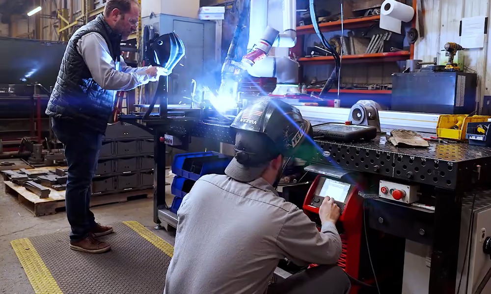
Modern power sources have moved well beyond simple voltage and wire feed speed control.Fronius, the welding technology partner for THG Automation’s robotic welding systems, offers a suite of advanced MIG processes. These features give fabricators precise control over heat input, spatter, and arc behavior that standard MIG cannot match.
Fronius Advanced MIG Processes
- PMC (Pulse Multi Control): Advanced pulsed MIG with independent control over pulse shape and energy for a stable, low-spatter arc.
- PMC Mix: Alternates between pulsed and cold phases to reduce heat input while maintaining deposition rate.
- CMT Welding Process (Cold Metal Transfer): Wire retracts during short circuiting to mechanically assist droplet detachment — virtually zero spatter and extremely low heat input.
- CMT Pulse: Combines CMT short circuit phases with pulsed arc phases for independent heat and deposition control.
- CMT Cycle Step: Adds a cooling phase between CMT cycles for demanding thin material and gap-bridging applications.
- LSC (Low Spatter Control): Electronically controls the short circuit break, eliminating conventional short circuit spatter.
- And more.
Fronius has pioneered pulsed MIG welding. However, their technology has advanced far beyond regular pulsed MIG. The CMT and CMT Pulse can achieve what typical pulsed or spray MIG never could, as one example.
Cobot Welding for Small and Mid-Size Shops
Small and mid-sized shops can use collaborative robotic MIG welding systems to consistently produce high quality welds. This goes for high-mix and complex parts too, not just simple table-welded parts. With the right robotic system, a small shop can improve their results dramatically. For example, Funkhouser Racecars, a small California shop, increased its output by 700% using our MIG welding cobot system and advanced Fronius robot welding features.
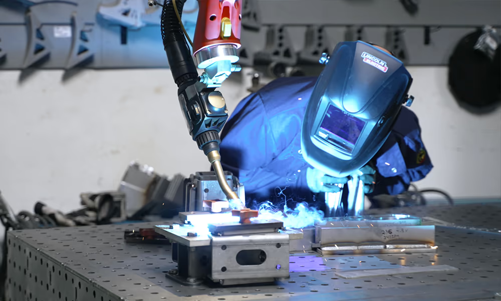
No coding skills needed or previous robotic welding experience. And no compromise either. THG Automation systems are built from the ground up with a modular architecture that lets you add a table or floor-mounted positioner, coordinated motion, multi-welding processes, expand the weld table, add linear rails, and more. We take what’s best of traditional robotics and provide it in a simple-to-use cobot form for small shops too.
If this sounds like something you want to explore, talk to our fabrication experts. We validate the process before commitment and help shops dramatically improve throughput, quality, and consistency.